Configuración de Interfaces del Router

Configuración de Interfaces del Router

Configuración de Interfaces del Router
5

Resumen

Aprende a configurar dos interfaces activas en un router con Cisco IOS. ¡¡Empieza a aprender CCNA 200-301 gratis ahora mismo!!

¡Bienvenido!: Este tema forma parte del Módulo 10 del curso de Cisco CCNA 1, para un mejor seguimiento del curso puede ir a la sección CCNA 1 para guiarte del índice.

1. Configurar Interfaces de Routers

En este punto, los routers tienen sus configuraciones básicas. El siguiente paso es configurar sus interfaces. Esto se debe a que los dispositivos finales no pueden acceder a los routers hasta que se configuran las interfaces. Hay muchos tipos diferentes de interfaces disponibles en los routers Cisco. Por ejemplo, el Router Cisco ISR 4321 está equipado con dos interfaces Gigabit Ethernet:

  • GigabitEthernet 0/0/0 (G0/0/0)
  • GigabitEthernet 0/0/1 (G0/0/1)

La tarea de configurar una interfaz de Router es muy similar a un SVI de administración en un Switch. Específicamente, incluye la emisión de los siguientes comandos:

Router(config)# interface tipo-y-numero
Router(config-if)# description texto-descripcion
Router(config-if)# ip address ipv4-address mascara-subred
Router(config-if)# ipv6 address ipv6-address/prefijo-longitud
Router(config-if)# no shutdown

Nota: Cuando se habilita una interfaz de Router, se deben mostrar mensajes de información que confirman el enlace habilitado.

Aunque el comando de descripción no es necesario para habilitar una interfaz, es una buena práctica usarlo. Puede ser útil para solucionar problemas en redes de producción al proporcionar información sobre el tipo de red conectada. Por ejemplo, si la interfaz se conecta a un ISP o proveedor de servicios, el comando de descripción sería útil para ingresar la conexión de terceros y la información de contacto.

Nota: El texto descriptivo está limitado a 240 caracteres.

El uso del comando no shutdown activa la interfaz y es similar a encender la interfaz. La interfaz también debe estar conectada a otro dispositivo, como un Switch o un Router, para que la capa física esté activa.

Nota: En las conexiones entre routers donde no hay un Switch Ethernet, ambas interfaces de interconexión deben estar configuradas y habilitadas.

2. Ejemplo Configurar Interfaces de Router

En este ejemplo, se habilitarán las interfaces conectadas directamente de R1 en el diagrama de topología.

Ejemplo configuración básica Router

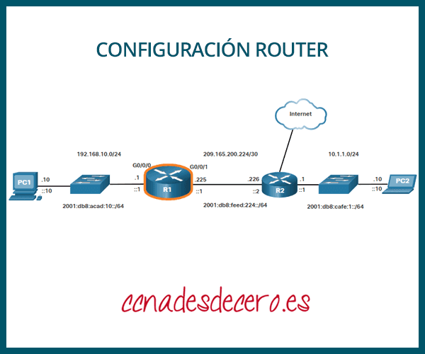
Para configurar las interfaces en R1, usa los siguientes comandos.

R1> enable
R1# configure terminal
Enter configuration commands, one per line.
End with CNTL/Z.
R1(config)# interface gigabitEthernet 0/0/0
R1(config-if)# description Enlace a LAN
R1(config-if)# ip address 192.168.10.1 255.255.255.0
R1(config-if)# ipv6 address 2001:db8:acad:10::1/64
R1(config-if)# no shutdown
R1(config-if)# exit
R1(config)#
*Aug 1 01:43:53.435: %LINK-3-UPDOWN: Interface GigabitEthernet0/0/0, changed state to down
*Aug 1 01:43:56.447: %LINK-3-UPDOWN: Interface GigabitEthernet0/0/0, changed state to up
*Aug 1 01:43:57.447: %LINEPROTO-5-UPDOWN: Line protocol on Interface GigabitEthernet0/0/0, changed state to up
R1(config)#
R1(config)#
R1(config)# interface gigabitEthernet 0/0/1
R1(config-if)# description Enlace a R2
R1(config-if)# ip address 209.165.200.225 255.255.255.252
R1(config-if)# ipv6 address 2001:db8:feed:224::1/64
R1(config-if)# no shutdown
R1(config-if)# exit
R1(config)#
*Aug 1 01:46:29.170: %LINK-3-UPDOWN: Interface GigabitEthernet0/0/1, changed state to down
*Aug 1 01:46:32.171: %LINK-3-UPDOWN: Interface GigabitEthernet0/0/1, changed state to up
*Aug 1 01:46:33.171: %LINEPROTO-5-UPDOWN: Line protocol on Interface GigabitEthernet0/0/1, changed state to up
R1(config)#

Nota: Observa los mensajes informativos que nos informan que G0/0/0 y G0/0/1 están habilitados.

3. Verificar la Configuración de la Interfaz

Hay varios comandos que pueden usarse para verificar la configuración de la interfaz. El más útil de estos es el comando show ip interface brief y show ipv6 interface brief, como se muestra en el ejemplo.

R1# show ip interface brief
Interface                           IP-Address            OK?   Method  Status Protocol
GigabitEthernet0/0/0   192.168.10.1         YES   manual    up      up
GigabitEthernet0/0/1   209.165.200.225 YES   manual   up     up
Vlan1 unassigned                                           YES unset administratively     down   down
R1# show ipv6 interface brief
GigabitEthernet0/0/0     [up/up]
FE80::201:C9FF:FE89:4501
2001:DB8:ACAD:10::1
GigabitEthernet0/0/1    [up/up]
FE80::201:C9FF:FE89:4502
2001:DB8:FEED:224::1
Vlan1                                  [administratively down/down]
unassigned
R1#

4. Comandos de Verificación de Configuración

La tabla resume los comandos show más populares utilizados para verificar la configuración de la interfaz.

ComandosDescripción
show ip interface brief
show ipv6 interface brief
La salida muestra todas las interfaces, sus direcciones IP y su estado actual. Las interfaces configuradas y conectadas deben mostrar un estado de “up” y un protocolo de “up”. Cualquier otra cosa indicaría un problema con la configuración o el cableado.
show ip route
show ipv6 route
Muestra el contenido de las tablas de enrutamiento IP almacenadas en la RAM.
show interfaces
Muestra estadísticas para todas las interfaces en el dispositivo. Sin embargo, este comando solo mostrará la información de direccionamiento IPv4.
show ip interfaces
Muestra las estadísticas de IPv4 para todas las interfaces en un Router.
show ipv6 interface
Muestra las estadísticas de IPv6 para todas las interfaces en un Router.

Haz clic en cada botón para ver la salida del comando para cada comando de verificación de configuración.

R1# show ip interface brief
Interface              IP-Address      OK? Method Status                Protocol 
GigabitEthernet0/0/0   192.168.10.1    YES manual up                    up 
GigabitEthernet0/0/1   209.165.200.225 YES manual up                    up 
Vlan1                  unassigned      YES unset  administratively down down

R1# show ipv6 interface brief
GigabitEthernet0/0/0       [up/up]
    FE80::201:C9FF:FE89:4501
    2001:DB8:ACAD:10::1
GigabitEthernet0/0/1       [up/up]
    FE80::201:C9FF:FE89:4502
    2001:DB8:FEED:224::1
Vlan1                      [administratively down/down]
    unassigned 
R1#

R1# show ip route
Codes: L - local, C - connected, S - static, R - RIP, M - mobile, B - BGP
       D - EIGRP, EX - EIGRP external, O - OSPF, IA - OSPF inter area 
       N1 - OSPF NSSA external type 1, N2 - OSPF NSSA external type 2
       E1 - OSPF external type 1, E2 - OSPF external type 2
       i - IS-IS, su - IS-IS summary, L1 - IS-IS level-1, L2 - IS-IS level-2
       ia - IS-IS inter area, * - candidate default, U - per-user static route
       o - ODR, P - periodic downloaded static route, H - NHRP, l - LISP
       a - application route
       + - replicated route, % - next hop override, p - overrides from PfR
Gateway of last resort is not set
      192.168.10.0/24 is variably subnetted, 2 subnets, 2 masks
C        192.168.10.0/24 is directly connected, GigabitEthernet0/0/0
L        192.168.10.1/32 is directly connected, GigabitEthernet0/0/0
      209.165.200.0/24 is variably subnetted, 2 subnets, 2 masks
C        209.165.200.224/30 is directly connected, GigabitEthernet0/0/1
L        209.165.200.225/32 is directly connected, GigabitEthernet0/0/1
R1#

R1# show ipv6 route
IPv6 Routing Table - default - 5 entries
Codes: C - Connected, L - Local, S - Static, U - Per-user Static route
       B - BGP, R - RIP, H - NHRP, I1 - ISIS L1
       I2 - ISIS L2, IA - ISIS interarea, IS - ISIS summary, D - EIGRP
       EX - EIGRP external, ND - ND Default, NDp - ND Prefix, DCE - Destination
       NDr - Redirect, RL - RPL, O - OSPF Intra, OI - OSPF Inter
       OE1 - OSPF ext 1, OE2 - OSPF ext 2, ON1 - OSPF NSSA ext 1
       ON2 - OSPF NSSA ext 2, a - Application
C   2001:DB8:ACAD:10::/64 [0/0]
     via GigabitEthernet0/0/0, directly connected
L   2001:DB8:ACAD:10::1/128 [0/0]
     via GigabitEthernet0/0/0, receive
C   2001:DB8:FEED:224::/64 [0/0]
     via GigabitEthernet0/0/1, directly connected
L   2001:DB8:FEED:224::1/128 [0/0]
     via GigabitEthernet0/0/1, receive
L   FF00::/8 [0/0]
     via Null0, receive
R1#

R1# show interfaces gig0/0/0
GigabitEthernet0/0/0 is up, line protocol is up 
  Hardware is ISR4321-2x1GE, address is a0e0.af0d.e140 (bia a0e0.af0d.e140)
  Description: Link to LAN
  Internet address is 192.168.10.1/24
  MTU 1500 bytes, BW 100000 Kbit/sec, DLY 100 usec, 
     reliability 255/255, txload 1/255, rxload 1/255
  Encapsulation ARPA, loopback not set
  Keepalive not supported 
  Full Duplex, 100Mbps, link type is auto, media type is RJ45
  output flow-control is off, input flow-control is off
  ARP type: ARPA, ARP Timeout 04:00:00
  Last input 00:00:01, output 00:00:35, output hang never
  Last clearing of "show interface" counters never
  Input queue: 0/375/0/0 (size/max/drops/flushes); Total output drops: 0
  Queueing strategy: fifo
  Output queue: 0/40 (size/max)
  5 minute input rate 0 bits/sec, 0 packets/sec
  5 minute output rate 0 bits/sec, 0 packets/sec
     1180 packets input, 109486 bytes, 0 no buffer
     Received 84 broadcasts (0 IP multicasts)
     0 runts, 0 giants, 0 throttles 
     0 input errors, 0 CRC, 0 frame, 0 overrun, 0 ignored
     0 watchdog, 1096 multicast, 0 pause input
     65 packets output, 22292 bytes, 0 underruns
     0 output errors, 0 collisions, 2 interface resets
     11 unknown protocol drops
     0 babbles, 0 late collision, 0 deferred
     1 lost carrier, 0 no carrier, 0 pause output
     0 output buffer failures, 0 output buffers swapped out
R1#

R1# show ip interface g0/0/0
GigabitEthernet0/0/0 is up, line protocol is up
  Internet address is 192.168.10.1/24
  Broadcast address is 255.255.255.255
  Address determined by setup command
  MTU is 1500 bytes
  Helper address is not set
  Directed broadcast forwarding is disabled
  Outgoing Common access list is not set 
  Outgoing access list is not set
  Inbound Common access list is not set 
  Inbound  access list is not set
  Proxy ARP is enabled
  Local Proxy ARP is disabled
  Security level is default
  Split horizon is enabled
  ICMP redirects are always sent
  ICMP unreachables are always sent
  ICMP mask replies are never sent
  IP fast switching is enabled
  IP Flow switching is disabled
  IP CEF switching is enabled
  IP CEF switching turbo vector
  IP Null turbo vector
  Associated unicast routing topologies:
        Topology "base", operation state is UP
  IP multicast fast switching is enabled
  IP multicast distributed fast switching is disabled
  IP route-cache flags are Fast, CEF
  Router Discovery is disabled
  IP output packet accounting is disabled
  IP access violation accounting is disabled
  TCP/IP header compression is disabled
  RTP/IP header compression is disabled
  Probe proxy name replies are disabled
  Policy routing is disabled
  Network address translation is disabled
  BGP Policy Mapping is disabled
  Input features: MCI Check
  IPv4 WCCP Redirect outbound is disabled
  IPv4 WCCP Redirect inbound is disabled
  IPv4 WCCP Redirect exclude is disabled
R1#

R1# show ipv6 interface g0/0/0
GigabitEthernet0/0/0 is up, line protocol is up
  IPv6 is enabled, link-local address is FE80::868A:8DFF:FE44:49B0
  No Virtual link-local address(es):
  Description: Link to LAN
  Global unicast address(es):
    2001:DB8:ACAD:10::1, subnet is 2001:DB8:ACAD:10::/64
  Joined group address(es):
    FF02::1
    FF02::1:FF00:1
    FF02::1:FF44:49B0
  MTU is 1500 bytes
  ICMP error messages limited to one every 100 milliseconds
  ICMP redirects are enabled
  ICMP unreachables are sent
  ND DAD is enabled, number of DAD attempts: 1
  ND reachable time is 30000 milliseconds (using 30000)
  ND NS retransmit interval is 1000 milliseconds
R1#

5. Comprobador de Sintaxis – Configurar Interfaces

Utiliza este comprobador de sintaxis para practicar la configuración de la interfaz GigabiteThemet 0/0 en un router.

  • Describir el enlace como ‘Enlace a LAN’.
  • Configurar la dirección IPv4 192.168.10.1 con la máscara de subred 255.255.255.0.
  • Configurar la dirección IPv6 como 2001:db8:acad:10: :1 con la longitud del prefijo /64.
  • Activar la interfaz.

  • Ingresa al modo de configuración global.
R1#configure terminal
Enter configuration commands, one per line. End with CNTL/Z.
  • Configura la interfaz GigabitEthernet 0/0/0.
R1(config)#interface gigabitethernet 0/0/0
  • Describe el enlace como “Enlace a LAN”.
R1(config-if)#description Enlace a LAN
  • Configura la interfaz con una dirección IPv4192.168.10.1 y una máscara de subred 255.255.255.0
R1(config-if)#ip address 192.168.10.1 255.255.255.0
  • Configura la interfaz con la dirección IPv6 2001:db8:acad:10::1 y la longitud del prefijo /64.
R1(config-if)#ipv6 address 2001:db8:acad:10::1/64
  • Habilita la interfaz y regrese al modo de configuración global.
R1(config-if)#no shutdown
\*Aug 1 01:43:53.435: %LINK-3-UPDOWN: Interface GigabitEthernet0/0/0, changed state to down
\*Aug 1 01:43:56.447: %LINK-3-UPDOWN: Interface GigabitEthernet0/0/0, changed state to up
\*Aug 1 01:43:57.447: %LINEPROTO-5-UPDOWN: Line protocol on Interface GigabitEthernet0/0/0, changed state to up
R1(config-if)#exit
R1#

Has configurado correctamente la configuración inicial en el router R1.

Glosario: Si tienes dudas con algún término especial, puedes consultar este diccionario de redes informáticas.

¡Listo! Sigue visitando nuestro blog de curso de redes, dale Me Gusta a nuestra fanpage; y encontrarás más herramientas y conceptos que te convertirán en todo un profesional de redes.